


Quadruped robots must keep power and data connections stable while the machine walks, turns, climbs and encounters impact. Their external cables move with the platform and may also be exposed to rain, dust, accidental pulling and repeated maintenance.
At the same time, a robot may need to connect cameras, LiDAR units, GNSS receivers, communication modules and mission-specific payloads. Its external interfaces must therefore do more than provide electrical continuity. They must support mechanical retention, environmental protection, signal integrity, error prevention and practical field service.
Public technical documentation from Rainbow Robotics provides a useful real-world reference. Its maintenance manual states that the RBQ10 interface uses a MOCO F Series waterproof connector. This article separates that confirmed application fact from the general interface information and connector-platform capabilities used in the engineering analysis.
1. A documented use of the MOCO F Series
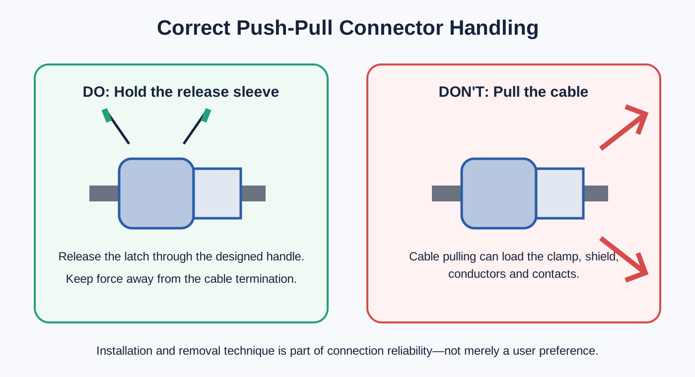
Rainbow Robotics' Connector Attachment/Detachment page states that the RBQ10 interface connector uses a MOCO F Series waterproof connector. The same page explains that, once engaged, the connector is not released by vibration or by pulling the wire. To remove it safely, the operator must hold the connector handle rather than apply force to the cable outside that area.
The manual also instructs the user to align the red marks, press the connector handle until engagement is complete, and then verify the connection.
These instructions reveal two fundamental requirements for a mobile robot interface:
- The mated connection must remain mechanically stable during robot motion and cable disturbance.
- Maintenance force must be applied through the designed release mechanism, not through the cable termination.
The online page does not show a publication date. Its current footer displays © 2026 Rainbow Robotics, so it is most accurately described as current online manual content rather than a dated announcement.
2. Why removal technique matters
In a push-pull self-latching connector, the plug forms a mechanical lock after correct mating. A normal axial load on the cable should not be treated as a release command. Removal is performed by operating the designated handle or release sleeve so that the locking mechanism disengages.
This separates operating conditions from maintenance actions:
- During operation, vibration and cable movement should not unintentionally release the connector.
- During service, the operator can deliberately unlock the connector without rotating it through multiple turns.
- When a cable is accidentally pulled, the termination is not intended to serve as the release mechanism.
Pulling directly on the cable can transfer force to the rear collet, jacket, shield termination, solder joint or crimp, conductor and internal insulator. The damage may not immediately appear as an open circuit. It may instead produce elevated contact resistance, intermittent communication, degraded shielding or reduced sealing performance.
For that reason, a handling instruction in a maintenance manual is not a minor user preference. It is part of the reliability strategy for the complete interface.
3. Why quadruped robot interfaces are demanding
Dynamic mechanical loads
A quadruped repeatedly accelerates, stops, turns, raises and lands its legs. The interface must tolerate changing loads while the cable is secured so that its weight and movement do not continuously act on the termination.
Frequent module changes
Payloads and sensors may be installed or replaced according to the mission. The interface must support fast maintenance without sacrificing positive locking or connection verification.
Water and contamination
Outdoor and industrial environments can expose interfaces to moisture, dust and dirt. Sealing depends on the mated pair, cable diameter, rear hardware, panel mounting and protective caps—not on the connector name alone.
Mixed electrical functions
Battery power, auxiliary power, CAN and Ethernet have different current, grounding, shielding and signal-integrity requirements, even when they use similar circular housings.
4. What the public RBQ interface architecture shows
Rainbow Robotics' External Port Information page documents two panel layouts. One visible distinction is the naming of the two USB-C ports: version 1 uses VISION and MOTION, while version 2 uses U-PC and R-PC.
Both versions include power, combined power-and-communication functions, emergency-stop connectivity and direct computer access. The documented specifications relevant to this analysis are summarized below.
| Interface | Publicly documented function | Engineering focus |
|---|---|---|
| POWER | VCC and GND; 42.0–58.4 V battery power; maximum 5 A. | Current capacity, contact resistance, temperature rise, voltage drop, polarity and live-mating policy. |
| PWR-CAN / PWR/CAN | VCC, GND, CAN High and CAN Low; 42.0–58.4 V battery power; maximum 10 A; CAN connected to the robot computer. | Power return, CAN pair integrity, isolation, shielding, grounding and switching noise. |
| 12V-LAN, version 1 | 12 V, maximum 2 A, plus two Ethernet pairs; Fast Ethernet at 100 Mbps. | Two-pair mapping, twist preservation, shield continuity and power-to-signal coupling. |
| 12V/LAN, version 2 | A 12-contact interface with four Gigabit Ethernet pairs, GND, +12 V and two reserve positions; camera-power note of 2–3 A. | Four-pair geometry, impedance, crosstalk, pair skew, termination quality and channel testing. |
5. POWER: a two-contact port is not a simple design problem
The public POWER interface contains VCC and GND and carries a 42.0–58.4 V battery supply with a stated maximum current of 5 A. Although the pin count is low, the design questions are substantial.
An engineer should verify:
- working and maximum voltage;
- continuous and transient current;
- contact resistance and allowable temperature rise;
- conductor cross-section and cable voltage drop;
- temperature derating and enclosure conditions;
- creepage, clearance and insulation requirements;
- whether the interface may be mated or unmated while energized;
- polarity protection and keying;
- rear strain relief and cable support.
A contact rating measured under one laboratory condition does not automatically remain valid in a hot enclosure or when several contacts carry current simultaneously. The rating must be interpreted for the exact insert, cable and operating environment.
If an external load has high inrush current, the connector should not be expected to act as an uncontrolled power switch. The system power sequence and maintenance procedure must be defined accordingly.
6. PWR-CAN: combining power and control data
The documented PWR-CAN interface combines a battery supply with CAN High and CAN Low. This arrangement can reduce the number of panel openings and cables required for an external module, but it is not merely a four-wire wiring exercise.
Preserve the CAN differential pair
CAN High and CAN Low should remain a twisted pair for as much of the channel as possible. Excessive untwisting near the connector can increase common-mode susceptibility and create an impedance discontinuity. A typical high-speed CAN network uses approximately 120-ohm characteristic-impedance cable and termination at both ends of the bus.
The connector is not itself the bus terminator, but contact assignment, pair separation and rear termination all affect the channel.
Control the power-return path
A 10 A power circuit can create voltage drop and switching noise in the return path. If the communication reference and power return are handled without a defined grounding strategy, power noise may affect the transceiver.
The design review should therefore address:
- whether the CAN transceiver is isolated;
- whether signal ground and power ground are common;
- where the cable shield is terminated;
- whether connected devices can develop a ground-potential difference;
- how power-switching transients are controlled;
- how power and signal contacts are arranged within the insert.
7. 100 Mbps and Gigabit Ethernet require different thinking
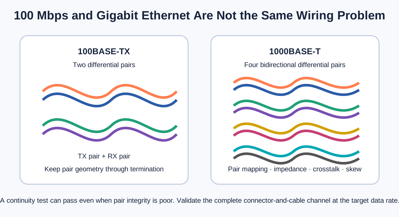
The first public panel version uses a 12V-LAN interface with two Ethernet pairs and 100 Mbps Fast Ethernet. The second uses a 12-contact 12V/LAN interface with four Gigabit Ethernet pairs.
This is more than a change in pin count.
100BASE-TX
100BASE-TX commonly uses two differential pairs: one transmit pair and one receive pair. Combining those pairs with 12 V power can produce a compact single-cable interface for a peripheral. The cable assembly still needs controlled pair mapping, limited untwist at the connector, adequate separation from power conductors and continuous shielding where required.
1000BASE-T
1000BASE-T commonly uses all four differential pairs for bidirectional transmission. In addition to requiring more contacts, it places greater emphasis on pair geometry, impedance, near-end and far-end crosstalk, pair-to-pair delay and termination consistency.
A cable can pass a simple continuity test and still fail to provide a stable Gigabit link. Incorrect pair mapping, excessive untwist, poor shield termination or mechanical deformation can lead to link-rate fallback, packet loss or intermittent operation.
For a Gigabit assembly, validation may therefore include channel analysis, link negotiation checks, traffic testing or bit-error testing, depending on project risk.
8. Why the MOCO F Series fits this class of problem
MOCO's public catalog download page describes the F Series as an outdoor half-shell-keyed connector platform with 2–27 contacts, IP68 options and vibration-resistant positioning. MOCO's F Series product information also describes push-pull self-latching, multipole configurations and 360-degree screening.
Push-pull self-latching
A push-pull latch provides positive engagement while allowing deliberate release through the connector handle. It is well suited to external modules that need regular installation or replacement.
However, the words “push-pull” or “vibration resistant” should not be treated as a substitute for a quantified project requirement. If an application requires a specific vibration spectrum, acceleration, duration or interruption limit, the exact connector and cable assembly should be verified against those conditions.
Half-shell keying
Half-shell keying helps orient the plug and receptacle. On a panel with several similar interfaces, it reduces the risk of misaligned mating. Complete error prevention may also require different insert patterns, shell sizes, mechanical coding, colors and durable panel labels.
Waterproof configurations
The F Series platform can provide IP68 configurations, but the technically accurate statement is:
It would be incorrect to assume that every F Series variant, every unmated state or every cable diameter provides the same protection.
Cable diameter and rear sealing
Internal MOCO training material distinguishes waterproof and non-waterproof F Series rear structures and notes additional components associated with shield compression and sealing. It also lists cable-diameter ranges for different shell sizes.
This reinforces a key engineering rule: the connector and cable must be selected together. A cable that is too small may not be compressed sufficiently for retention and sealing; a cable that is too large may prevent correct rear assembly or damage the sealing system.
360-degree shielding
A metal connector can provide a circumferential shield-termination path, but the connector is only one element in the EMC chain. Effective shielding also depends on the cable braid or foil, rear termination, plug-to-receptacle shell contact, receptacle-to-chassis connection and system grounding strategy.
If a full cable shield is reduced to a long, thin drain-wire connection, high-frequency shielding performance can be degraded. For CAN and especially Gigabit Ethernet, connector, cable and termination should be evaluated as one channel.
9. IP68: questions that must be answered
IP68 is often shortened to “fully waterproof,” but that wording is not sufficiently precise for procurement or engineering. Before accepting an IP claim, confirm:
- Does the rating apply when the plug and receptacle are mated?
- What water depth and exposure duration were used?
- Was a specified cable diameter required?
- Does the rear termination require a gasket, shield-compression hardware or potting?
- Does the panel receptacle require an installation seal?
- Does an unused receptacle require a protective cap?
- Are different receptacle styles rated differently?
- Must seals be inspected after repeated mating cycles?
- Does the project also require salt-spray, thermal-cycling or pressure-change validation?
The final environmental result belongs to the complete installed interface, not to a series name in isolation.
10. A practical connector selection checklist
11. What this documented application teaches
The Rainbow Robotics maintenance documentation confirms an actual use of the MOCO F Series on the RBQ10 interface. More importantly, the wider public interface documentation shows why a robot connector must be treated as part of a complete system.
Long-term connection reliability depends on all of the following:
- correct voltage and current selection;
- appropriate contact and cable structures for CAN and Ethernet;
- positive mechanical retention;
- complete environmental sealing;
- continuous shielding and intentional grounding;
- cable support and strain relief;
- error-prevention measures;
- correct attachment and removal;
- repeatable assembly and inspection.
The MOCO F Series provides a technical platform that can support push-pull latching, waterproof configurations, half-shell keying and shielding. The final configuration must still be selected around the real port function, exact part number, cable, environment and verification plan.
Frequently Asked Questions
Does the RBQ10 use a MOCO connector?
Yes. Rainbow Robotics' online maintenance manual explicitly states that the RBQ10 interface connector uses a MOCO F Series waterproof connector.
Are all RBQ external ports MOCO connectors?
The public sources do not establish that. The external-port page documents functions and pin assignments, but it does not identify the manufacturer of every connector.
Which F Series part number is used?
The public Rainbow Robotics pages do not disclose the exact part number, shell size or insert configuration. It should not be inferred from appearance or pin count.
Is the specific RBQ10 connector confirmed as IP68?
The available Rainbow Robotics page identifies an F Series waterproof connector but does not publish the exact part number and rating. MOCO offers IP68 F Series configurations; the rating of a specific assembly must be confirmed from its part-number documentation and mating conditions.
Why should the cable not be pulled during removal?
Pulling the cable can load the rear clamp, shield termination, conductors and contacts. The Rainbow Robotics manual instructs the user to hold the connector handle for safe removal.
Can power and CAN share one circular connector?
Yes, provided the design addresses current, temperature rise, return path, CAN pair integrity, shielding, grounding and power-switching noise.
Can a 100 Mbps cable assembly be upgraded directly to Gigabit Ethernet?
Not necessarily. Gigabit Ethernet commonly requires four controlled differential pairs and tighter control of pair mapping, impedance, crosstalk, skew and termination.
Does a metal connector guarantee good EMC performance?
No. The cable shield, rear termination, shell contact, chassis connection and grounding strategy must form a continuous low-impedance path.
Sources and attribution
- Rainbow Robotics — Connector Attachment/Detachment. Confirms use of the MOCO F Series waterproof connector and provides handling instructions. No publication date is shown on the page.
- Rainbow Robotics — External Port Information. Documents the two panel layouts, port functions, pin assignments and electrical information. It does not attribute every port to MOCO.
- MOCO Connectors — Catalog Download. Provides the current F Series catalog entry and product-platform description.
Technical values in this article are attributed to the linked public sources. Product-platform capabilities must be verified against the current specification for the exact part number selected.
Design the interface as a complete system
For a robot power, CAN, Ethernet or mixed-signal interface, define the electrical load, signal rate, cable, environment, mating condition and test plan before selecting the connector configuration.
